
- Member ID
- #18787
- Messages
- 9
- Reactions
- 10
- Likes
- 2
- City
- Springfield
- State
- MO
- Country
- United States
- Vehicle
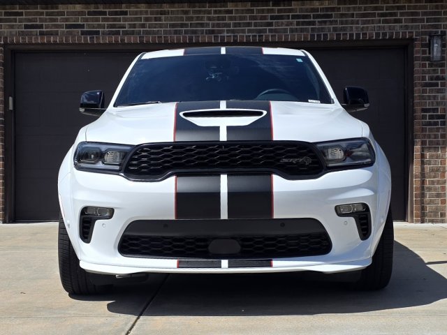
- 2026 DDHC Jailbreak
I installed fog lamps on my 2026 DDHC Jailbreak. Below is the complete parts list and step-by-step process.
PARTS
NOTE
To check if your Durango already has fog lamp wiring:
Option 1 (Harder):
BCM ACCESS
The BCM is located behind the passenger-side kick panel near the door.
Steps:
ADDING MISSING WIRES (BRIDGING)
Step 1: Disconnect Battery Ground
Step 2: Terminals Required
INSTALL HEADLAMP/FOG LAMP SWITCH
Step 1: Remove switch bezel
Step 2: Disconnect original Headlamp switch
Step 2: Install the headlamp/fog lamp switch (68474269AB)
Step 3: Reinstall switch bezel
PROGRAMMING (REQUIRED)
The BCM must be configured or the fog lamps will not function.
Required Tools:
Dealer can enable fog lamps via flashing BCM and adding sales code LNV
Note: Tazer may support this, I have not confirmed this
ALFAOBD PROGRAMMING STEPS
Watch this Dodge Durango front bumper removal guide before starting:
PARTS
- 68474269AB – Headlamp and Fog Lamp Switch (x1)
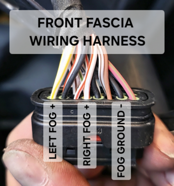
- 68622050AA – Front Fascia Wiring Harness (x1)
(Fits 2023–2026 with Adaptive Cruise Control / Fog Lamps / Park Sensors) - 6UZ34RXFAA – Fog Lamp Bezel, Right (x1)
- 6UZ35RXFAA – Fog Lamp Bezel, Left (x1)
- 68275510AC – Front Fog Lamp, Right (x1)
- 68275511AC – Front Fog Lamp, Left (x1)
- 68090949AA – Fog Lamp Screws (x6)
- 06513822AA – Plastic Rivets (x4)
- 6512761AA – Metal Rivets (x2)
- 20 gauge wire
- 1718760-1 TE Connectivity MCON 1.2 terminals (x3)
(For Front End Module harness connector → Front Fascia harness) - 1-967067-1 TE Connectivity MQS wire seals (x3)
(For Front End Module harness connector) - SNAC-A061T-M2.8 JST female terminals (x2)
(For BCM Connector A & D) - 1/4" black braided expandable wiring loom (several feet)
NOTE
- If you have a 2022 or older Durango with Adaptive Cruise Control / Fog Lamps / Park Sensors, use wiring harness 68494441AA instead.
- If your 2024–2026 Durango Front End Module wiring harness is missing fog lamp wires, you will need to run bridge wires from the BCM to the front fascia wiring harness.
- Early 2024 models typically did not have the fog lamp wiring removed yet. However, Hellcat models are likely missing these wires across all years. It’s unclear exactly when in 2024 Dodge began de-contenting harnesses or which trim levels were affected.
To check if your Durango already has fog lamp wiring:
Option 1 (Harder):
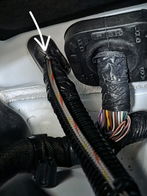
- Pull back the passenger-side fender splash shield and inspect wiring (see reference images).
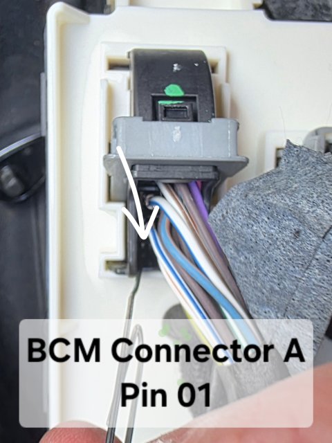
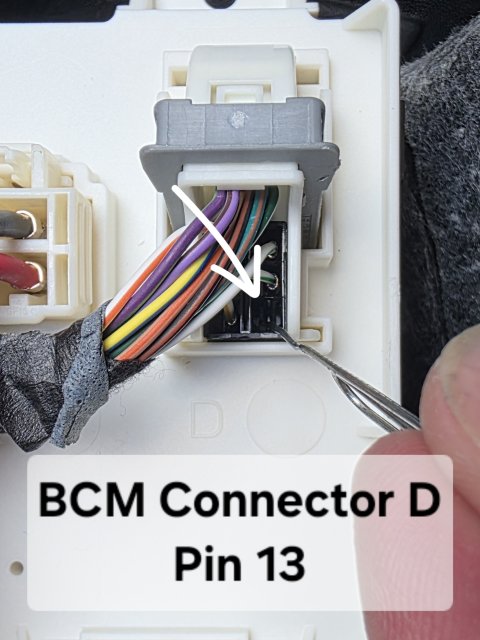
- Inspect BCM connectors:
- Connector A - Pin 01
- Connector D - Pin 13
BCM ACCESS
The BCM is located behind the passenger-side kick panel near the door.
Steps:
- Remove the plastic kick panel (pull outward from rear edge)
- Remove the silencer panel under the glove box (3 push pins)
- Remove two 10mm nuts at the bottom of the BCM
- Gently pull the bottom outward, then slide the BCM downward
ADDING MISSING WIRES (BRIDGING)
Step 1: Disconnect Battery Ground
Step 2: Terminals Required
- (3) Male terminals for Front End Module 16-pin connector
- TE Connectivity 1718760-1
- (2) Female terminals for BCM connectors
- SNAC-A061T-M2.8
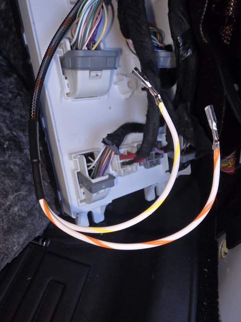
- BCM Connector A Pin 01 → White/Yellow (Left Fog)
- BCM Connector D Pin 13 → White/Orange (Right Fog)
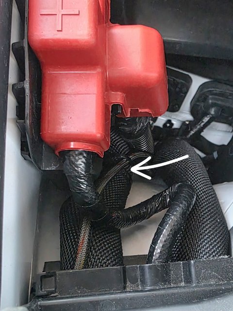
- Route both wires through the rubber firewall grommet into the engine bay
- Locate BCM Connector A and BCM Connector D
- Identify the correct cavities:
- Connector A – Pin 01 (Left Fog)
- Connector D – Pin 13 (Right Fog)
- Prepare your wires:
- Strip a small amount of insulation
- Crimp the SNAC-A061T-M2.8 female terminals securely onto each wire
- Insert the terminals into the BCM connector:
- Push each terminal into the correct cavity from the wire side (rear of connector)
- You should feel or hear a click when the terminal locks into place
- Gently tug on the wire to confirm it is fully seated and locked
- Do NOT force terminals—if it doesn’t click, it’s likely misaligned
- Verify orientation of the terminal (they only insert one way)
- Double-check you are in the correct connector and terminal location before inserting
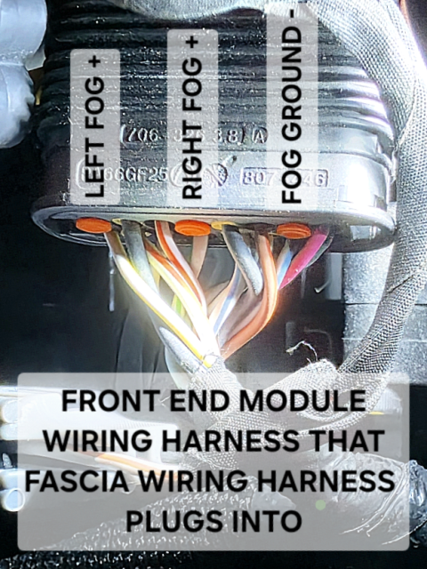
- Locate the 16-pin Front End Module connector (body-side harness)
- Identify correct orientation:
- View from the wire side (rear of connector)
- Lock tab facing downward
- Pins numbered left → right
- Identify the required cavities:
- Pin 1 → Left Fog (+)
- Pin 4 → Right Fog (+)
- Pin 7 → Ground
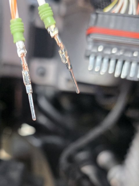
- Slide a 1-967067-1 wire seal onto each wire before crimping
- Strip a small amount of insulation
- Crimp the 1718760-1 terminals onto the wires using a proper crimp tool
- Locate the three orange cavity plugs in Pin 1, Pin 4 and Pin 7
- Carefully remove them using a pick or small tool
- Do not damage the connector housing
- Insert each terminal from the wire side (rear of connector):
- Left Fog wire → Pin 1
- Right Fog wire → Pin 4
- Ground wire → Pin 7
- Push firmly until you feel/hear a click
- Lightly tug each wire to confirm it is locked in place
- Double-check orientation—this is where most mistakes happen
- Do not force terminals; if it doesn’t click, it’s not aligned correctly
- Verify pin locations against your fascia harness before final assembly
- Ensure the wire seals are properly seated in the connector
- Ground the black wire to the factory ground stud on the frame rail near the 16-pin connector
INSTALL HEADLAMP/FOG LAMP SWITCH
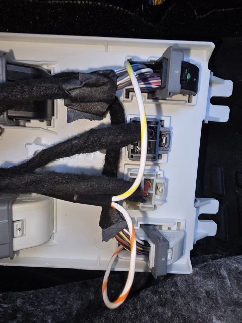
Step 1: Remove switch bezel
Step 2: Disconnect original Headlamp switch
Step 2: Install the headlamp/fog lamp switch (68474269AB)
Step 3: Reinstall switch bezel
PROGRAMMING (REQUIRED)
The BCM must be configured or the fog lamps will not function.
Required Tools:
- Security Gateway Bypass Module (Z-Automotive)
- OBDLink MX+
- AlfaOBD software
Dealer can enable fog lamps via flashing BCM and adding sales code LNV
Note: Tazer may support this, I have not confirmed this
ALFAOBD PROGRAMMING STEPS
- Connect
- Install SGW bypass (behind passenger-side center console kick panel)
- Plug in OBDII device
- Turn ignition to RUN (engine off)
- Select Vehicle
- Open AlfaOBD → Select Dodge → Durango
- Access BCM
- Select Body Control Module (correct year)
- Configuration
- Open “Car Configuration Change”
- Enable Fog Lamps
- Set CBC Features-LED Front Fog Lamps Present → Yes
- Set CBC Config I/O-Connector A Pin 01 and Connector D Pin 13: Front Fog Lamps Output Present → Yes
- Optional
- Set CBC Features-Front Fog Lamp Dropout Enabled → No
(Keeps fog lights on with high beams)
- Set CBC Features-Front Fog Lamp Dropout Enabled → No
- Write Changes
- Click “Start” and wait for completion
- Power Cycle
- Turn vehicle off, remove key, wait ~5 minutes
- 8mm socket
- 10mm socket
- Trim removal tool
- Push pin pliers
- 7/32" drill bit (metal rivets)
- T20 Torx bit (fog lamp screws)
- Narrow punch (for punching out center of plastic rivets)
- Hammer (if needed for assisting punching out center of plastic rivets)
- Wire crimp tool
Watch this Dodge Durango front bumper removal guide before starting:
Last edited:
-
 3
3
-
 1
1
- Show All

